Description
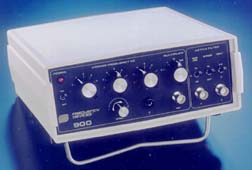
Frequency Devices' Model 900 instruments furnish the user with a 4- or 8-pole low-pass or high-pass instrument that has a field replaceable filter module and is tunable by front panel controls. The controls allow the user to select a corner frequency between 0.1 Hz and 49.9kHz with a resolution of 1:499 for each of the four selectable ranges.
The instrument exhibits an input impedance of 1 MegΩ shunted by 47 pF to a single ended signal source. When configured in the differential mode, the instrument has a common mode rejection ratio (CMRR) which exceeds 60 dB; in this mode the instrument presents an input impedance of 2 MegΩ shunted by 47pF to a double ended single source. Front panel gain control also enables the operator to select a gain factor of 0,10, or 20dB.
Features/Benefits:
- Plug-in Filter Module
- Adjustable Frequency Control
- Differential Input Amplifiers
- Adjustable Gain Control
- Off-set Adjustment
- BypassControl
- BNC ConnectorsforSignal l/O
An optional battery powered version is available and is particularly well suited to applications requiring isolation from an electrically noisy primary power source.
Applications
Compact size and manual rotary switch front panel controls make 900 instruments a popular, cost effective, easy-to-use solution for signal conditioning applications in the following areas:
- Anti-aliasing Filters
- Biomedical/Biotechnology Applications
- Data Recording/Playback
- Data Smoothing
- EKG/EEG Signal Filtering
- FDM/PCM Signal Filtering
- Medical Research
- Industrial Process Control
- Seismic Analysis
- Vibration Analysis
|
|
Chassis
|
| |
|
|
900C
|
Standard AC powered chassis |
| |
|
|
900B
|
AC powered, with battery powered option |
| |
|
| |
Available Low-Pass Models
|
| |
|
BUTTERWORTH |
| |
|
|
9L8B |
8-pole Butterworth |
| |
|
|
9L4B |
4-pole Butterworth |
| |
|
BESSEL |
| |
|
|
9L8L
|
8-pole Bessel |
| |
|
|
9L4L
|
4-pole Bessel |
| |
|
ELLIPTIC |
| |
|
|
9L8E
|
8-pole elliptic, 1.77, 80dB |
| |
|
|
9L8EY
|
8-pole elliptic, 2.00, 100dB |
| |
|
CONSTANT DELAY |
| |
|
|
9L8D80
|
8-pole constant delay, 80dB |
| |
|
|
9L8D10
|
8-pole constant delay, 100dB |
| |
Available High-Pass Models
|
| |
|
BUTTERWORTH |
| |
|
|
9H8B
|
8-pole Butterworth |
| |
|
|
9H4B
|
4-pole Butterworth |
| |
|
ELLIPTIC |
| |
|
|
9H8E
|
8-pole elliptic, 1.77, 80dB |
| |
|
|
9H8EY |
8-pole elliptic, 2.00, 100dB |
| |
|
|
|
|
Model 900
|
Tunable Active Filter Instruments
|
BLOCK DIAGRAM

Model 900
|
4 & 8-Pole
Low-Pass Filters
|
| Model |
9L4B |
9L4L |
9L8B |
9L8L |
| Product Specifications |
Transfer Function
Range fc |
4-Pole, Butterworth
0.1 Hz to 49.9 kHz |
4-Pole, Bessel
0.1 Hz to 49.9 kHz |
8-Pole, Bessel
0.1 Hz to 49.9 kHz |
8-Pole, Bessel
0.1 Hz to 49.9 kHz |
Theoretical Transfer
Characteristics |
Click to view
|
Click to view
|
Click to view
|
Click to view
|
| Tuning Resolution |
1 part in 499
within each decade |
1 part in 499
within each decade |
1 part in 499
within each decade |
1 part in 499
within each decade |
Passband Ripple
(theoretical) |
0.0 dB |
0.0 dB |
0.0 dB |
0.0 dB |
DC Voltage Gain
(non-inverting) |
0 ± 0.2 dB max.
0 ± 0.1 dB typ. |
0 ± 0.2 dB max.
0 ± 0.1 dB typ. |
0 ± 0.2 dB max.
0 ± 0.1 dB typ. |
0 ± 0.2 dB max.
0 ± 0.1 dB typ. |
Stopband
Attenuation Rate |
24 dB/octave |
24 dB/octave |
48 dB/octave |
48 dB/octave |
Cutoff Frequency
Accuracy
Stability
Amplitude
Phase |
fc ± 2% max.
± 2% max.
± 0.5% typ.
± 0.02% /°C max.
± 0.01% /°C typ.
-3 dB
-180° |
fr ± 2% max.
± 2% max.
± 0.5% typ.
± 0.02% /°C max.
± 0.01% /°C typ.
-3 dB
-121° |
fr ± 2% max.
± 2% max.
± 0.5% typ.
± 0.02% /°C max.
± 0.01% /°C typ.
-3 dB
-360° |
fr ± 2% max.
± 2% max.
± 0.5% typ.
± 0.02% /°C max.
± 0.01% /°C typ.
-3 dB
-182° |
Filter Attenuation
(theoretical) |
0.67 dB 0.80 fc
3.01 dB 1.00 fc
30.0 dB 2.37 fc
40.0 dB 3.16 fc |
1.86 dB 0.80 fc
3.01 dB 1.00 fc
30.0 dB 3.50 fc
40.0 dB 4.72 fc |
0.12 dB 0.80 fc
3.01 dB 1.00 fc
60.0 dB 2.37 fc
80.0 dB 3.16 fc |
1.91 dB 0.80 fc
3.01 dB 1.00 fc
60.0 dB 4.52 fc
80.0 dB 6.07 fc |
Total Harmonic
Distortion |
< - 90 dB typ. |
< - 90 dB typ. |
< - 90 dB typ. |
< - 90 dB typ. |
Wide Band Noise
(5 Hz - 2 MHz) |
200 µVrms typ. |
200 µVrms typ. |
200 µVrms typ. |
200 µVrms typ. |
Narrow Band Noise
(5 Hz - 100 kHz) |
50 µVrms typ. |
50 µVrms typ. |
50 µVrms typ. |
50 µVrms typ. |
Model 900
|
8-Pole
Low-Pass Filters
|
| Model |
9L8E |
9L8EY |
9L8D80 |
9L8D10 |
| Product Specifications |
Transfer Function
Range fc, fr |
8-Pole, 6 zero,
Elliptic
0.1 Hz to 49.9 kHz |
8-Pole, 6 zero,
Elliptic
0.1 Hz to 49.9 kHz |
8-Pole, 6 zero,
Constant Delay
0.1 Hz to 49.9 kHz |
8-Pole, 6 zero,
Constant Delay
0.1 Hz to 49.9 kHz |
Theoretical Transfer
Characteristics |
Click to view
|
Click to view
|
Click to view
|
Click to view
|
| Tuning Resolution |
1 part in 499
within each decade |
1 part in 499
within each decade |
1 part in 499
within each decade |
1 part in 499
within each decade |
Passband Ripple
(theoretical) |
± 0.035 dB |
-0.05 dB |
0.15 dB |
0.15 dB |
DC Voltage Gain
(non-inverting) |
0 ± 0.2 dB max.
0 ± 0.1 dB typ. |
0 ± 0.2 dB max.
0 ± 0.1 dB typ. |
0 ± 0.2 dB max.
0 ± 0.1 dB typ. |
0 ± 0.2 dB max.
0 ± 0.1 dB typ. |
Stopband
Attenuation |
-80 dB typ. |
-100 dB typ. |
-80 dB typ. |
-100 dB typ. |
Cutoff Frequency
Accuracy
Stability
Amplitude
Phase |
fr ± 2% max.
± 2% max.
± 0.5% typ.
± 0.02% /°C max.
± 0.01% /°C typ.
-0.035 dB
-323° |
fr ± 2% max.
± 2% max.
± 0.5% typ.
± 0.02% /°C max.
± 0.01% /°C typ.
-0.05 dB
-419° |
fc ± 2% max.
± 2% max.
± 0.5% typ.
± 0.02% /°C max.
± 0.01% /°C typ.
-3 dB
-306° |
fc ± 2% max.
± 2% max.
± 0.5% typ.
± 0.02% /°C max.
± 0.01% /°C typ.
-3 dB
-311° |
Filter Attenuation
(theoretical) |
0.035 dB 1.00 fr
3.01 dB 1.13 fr
60.0 dB 1.67 fr
80.0 dB 1.77 fr |
0.05 dB 1.00 fr
3.01 dB 1.06 fr
80.0 dB 1.83 fr
100.0 dB 2.00 fr |
3.01 dB 1.00 fc
60.0 dB 3.08 fc
80.0 dB 3.57 fc |
3.01 dB 1.00 fc
80.0 dB 4.45 fc
100.0 dB 5.20 fc |
Total Harmonic
Distortion |
< - 90 dB typ. |
< - 88 dB typ. |
< - 90 dB typ. |
< - 88 dB typ. |
Wide Band Noise
(5 Hz - 2 MHz) |
250 µVrms typ. |
250 µVrms typ. |
200 µVrms typ. |
200 µVrms typ. |
Narrow Band Noise
(5 Hz - 100 kHz) |
75 µVrms typ. |
75 µVrms typ. |
50 µVrms typ. |
50 µVrms typ. |
Model 900
|
4 & 8-Pole
High-Pass Filters
|
| Model |
9H4B |
9H8B |
9H8E |
9H8EY |
| Product Specifications |
Transfer Function
Range fc, fr |
4-Pole
Butterworth
0.1 Hz to 49.9 kHz |
8-Pole
Butterworth
0.1 Hz to 49.9 kHz |
8-Pole, 6 zero,
Elliptic
0.1 Hz to 49.9 kHz |
8-Pole, 6 zero,
Elliptic
0.1 Hz to 49.9 kHz |
Theoretical Transfer
Characteristics |
Click to view
|
Click to view
|
Click to view
|
Click to view
|
| Tuning Resolution |
1 part in 499
within each decade |
1 part in 499
within each decade |
1 part in 499
within each decade |
1 part in 499
within each decade |
Passband Ripple
(theoretical) |
0.0 dB |
0.0 dB |
± 0.035 dB |
-0.05 dB |
Voltage Gain
(non-inverting) |
0 ± 0.2 dB to 100 kHz
0 ± 0.5 dB to 120 kHz |
0 ± 0.2 dB to 100 kHz
0 ± 0.5 dB to 120 kHz |
0 ± 0.2 dB to 100 kHz max.
0 ± 0.5 dB to 120 kHz typ. |
0 ± 0.2 dB to 100 kHz max.
0 ± 0.5 dB to 120 kHz typ. |
| Power Bandwidth |
120 kHz |
120 kHz |
120 kHz |
120 kHz |
Stopband
Attenuation |
24 dB/octave |
48 dB/octave |
-80 dB typ. |
-100 dB typ. |
Cutoff Frequency
Accuracy
Stability
Amplitude
Phase |
fc ± 2% max.
± 2% max.
± 0.5% typ.
± 0.02% /°C max.
± 0.01% /°C typ.
-3 dB
-180° |
fc ± 2% max.
± 2% max.
± 0.5% typ.
± 0.02% /°C max.
± 0.01% /°C typ.
-3 dB
-360° |
fr ± 2% max.
± 2% max.
± 0.5% typ.
± 0.02% /°C max.
± 0.01% /°C typ.
-0.035 dB
-323° |
fr ± 2% max.
± 2% max.
± 0.5% typ.
± 0.02% /°C max.
± 0.01% /°C typ.
-0.05 dB
-419° |
Filter Attenuation
(theoretical) |
40 dB 0.31 fc
30 dB 0.42 fc
3.01 dB 1.00 fc
0.02 dB 2.00 fc |
80 dB 0.31 fc
60 dB 0.42 fc
3.01 dB 1.00 fc
0.00 dB 2.00 fc |
80 dB 0.56 fr
60.0 dB 0.60 fr
3.01 dB 0.88 fr
0.03 dB 1.00 fr
0.00 dB 2.00 fr |
100 dB 0.50 fr
80.0 dB 0.55 fr
3.01 dB 0.94 fr
0.03 dB 1.00 fr
0.00 dB 2.00 fr |
Total Harmonic
Distortion |
< - 88 dB typ. |
< - 88 dB typ. |
< - 88 dB typ. |
< - 88 dB typ. |
Wide Band Noise
(5 Hz - 2 MHz) |
400 µVrms typ. |
400 µVrms typ. |
400 µVrms typ. |
500 µVrms typ. |
Narrow Band Noise
(5 Hz - 100 kHz) |
100 µVrms typ. |
100 µVrms typ. |
100 µVrms typ. |
150 µVrms typ. |
Model 900
|
Location of Front Panel
Terminals and Controls
|
| A. POWER ON/OFF Switch: A two position toggle switch that interrupts/completes the internal DC power circuit and resets the battery protection circuit.
B. POWER Status Lamp: This red LED indicates whether or not the power to the analog filter circuitry of a Model 900 instrument is correct. With the POWER switch in the ON position the LED glows continuously if the internal DC power levels are correct, flashes for low DC power levels, and goes off for grossly improper DC power levels. See power lamp status, page 14.
C. CORNER FREQUENCY Selector Switch (0-400): This five position rotary switch selects the 100’s digit value of the corner frequency designator. The switch selectable values are 0, 100, 200, 300, and 400 in five discrete steps.
D. CORNER FREQUENCY Selector Switch (0-90): This ten position rotary switch selects the 10’s digit of the desired corner frequency between 0 and 90, in discrete increments of 10. |
E. CORNER FREQUENCY Selector Switch (0-9): This ten position rotary switch selects the 1’s digit of the desired corner frequency between 0 and 9, in discrete increments of 1.
F. MULTIPLIER Selector Switch: This four position rotary switch multiplies by a factor of either 0.1, 1, 10, or 100, the aggregate value set on the three CORNER FREQUENCY selector switches. (C, D & E).
G. GAIN Switch: This three position toggle switch selects an overall filter gain of either 0, 10, or 20dB.
H. BYPASS Switch: OUT and IN setting of this two position toggle switch routes the input signal to the internal low-pass filter or around it, respectively. For either case, the GAIN switch remains operational.
J. INPUT Switch: This three position toggle configures the instrument for either differential inputs (A-B), a single- ended input (A), or input nulling ( ) which grounds both the (A) and (B) input terminals. |
K. OFFSET Adjust: This adjustment is intended to zero the offset that results from the instruments own circuitry and does not provide for wide range offset to remove dc input signals.
L. GROUND Terminal: This “Banana” type test jack provides neat and secure access to the internal ground. This terminal is a convenient junction for grounding external system and measurement instrumentation and/or apparatus.
M. OUT Terminal: This terminal is a female BNC connector. The shield on the BNC is internally connected to the instrument ground.
N & O. (A) and (B) Input Terminals: This pair of shielded, female BNC connectors accept signal inputs (A) and (B). The instrument applies a non- inverting gain to input (A) and an equal but opposite inverting gain to input (B) while the GAIN switch sets the magnitude of differential gain to either 0, 10, or 20dB. The BNC shields have been internally connected to the instrument ground. |
Model 900
|
Controls and Terminals
|
Location of Rear Panel Terminals and Controls
P. IDENTIFICATION LABEL: This label identifies the filter type, serial number and date of manufacture.
Q. POWER designation: This label identifies operating power limits and fuse requirements of the instrument. |
R. POWER CONNECTION: Denotes plug and fuse location.
S. VOLTAGE Selector Switch: This two position switch determines the operating voltage (110 Vac or 220 Vac). |
At time of shipment, the voltage select switch is preset in the 110 Vac position. For 220 Vac operation, this switch must be rotated to the 220 Vac position. |
POWER Lamp Status
|
LAMP
STATUS
|
POWER
SOURCE
|
|
AC POWER LINE
|
INTERNAL BATTERY
|
ON
|
Operating Normally
Line and internal voltages are correct |
Operating Normally
Sufficient battery charge |
FLASHING
|
Possible Causes:
Low AC line voltage
Fault external causing power overload Internal instrument fault |
Possible Causes:
Batteries near exhaustion
(approximately 30 minutes of
operation remain) |
OFF
|
Possible Causes:
POWER Switch off
Momentary power line drop-out tripped protection circuit.*
Open line fuse |
Possible Causes:
POWER Switch off
Internal protection circuit
tripped.* |
| *Reset by cycling POWER Switch off then on. |
|
Filter Replacement Instructions:
Steps to Follow:
- Unplug (disconnect from Power) instrument.
- Turn chassis over.
- With black instrument supports facing up, remove mounting screws.
- Holding cover in place, turn unit to up-right position and remove top cover.
- Locate black filter module and carefully remove from channel board.
- Match replacement filter module pin locations with insertion holes in channel board and gently insert replacement module.
- Replace instrument top cover, carefully turn over and install in- strument supports and screws.
|
|
Model 900
|
Operation and Application
Guide Lines
|
| Initial Setup
Select desired operating voltage 110 Vac or 220 Vac. See note "S" page 14.
Set the POWER ON/OFF Switch to ON. A continuously lit POWER status lamp denotes proper internal dc voltages, an essential indication for battery powered models. Allow the instrument a three minute warm-up period to achieve thermal equilibrium.
To perform initial adjustment and/or operational testing, set the remaining front panel controls as follows:
- The three base CORNER FREQUENCY switches and the MULTIPLIER to the desired corner frequency...
- The OFFSET control to approximately mid-range...
- The GAIN switch to the desired value...
- The BYPASS switch to OUT...
- The INPUT switch to ground ( )...
Connect a dc-coupled oscilloscope, of vertical sensitivity 10mV/CM or better, or a digital voltmeter (DVM) to the instrument front panel BNC connector labeled OUT.
Set the OFFSET control for a zero-volt reading on the scope.
Subsequent changes of CORNER FREQUENCY, GAIN or BYPASS control settings will introduce a small dc output offset which should be zeroed for critical applications.
Leaving all other controls unchanged, set the Input Switch to (A-B) and apply a 5Vdc signal simultaneously to input BNCs (A) and (B). The voltage measured at the OUT BNC should be 5-5=OVdc. This completes preliminary test and adjustment.
|
Corner Frequency Selection
To select a corner frequency, simply set the three CORNER FREQUENCY switches and the MULTIPLIER switch for the desired numerical value.
The CORNER FREQUENCY switch weighings follow standard decimal positional convention.
The C, D and E switches combined can select base corner frequency values ranging from 1 to 499 Hz in 1Hz steps, with switch weighings as just described.
The accuracy of the corner frequency is improved by selecting the largest possible base frequency and down scaling by the MULTIPLIER. The greatest accuracy is obtained with the largest base 400, and the 0.1X MULTIPLIER switch 400 setting.
Relative accuracy of selected 40 Hz actual corner frequency for different multiplier switch settings.
The instrument utilizes a differential input amplifier to reject prevalent forms of electrical interference, while presenting desirable input characteristics to the signal source requiring filtering.
The differential Input
The differential input configuration is ideal for measuring the difference between two values rather than the values themselves. Bridge circuits utilizing strain gages, thermocouples and a variety of other types of transducers generate differential full scale output voltages in the order of millivolts that are often superimposed upon volt-level reference and noise values.
The importance of CMRR
In actual system environments, each signal and power return conductor can generate an interference voltage proportional to the net conductor resistance and the electrical current level. Any such interference voltages appear as common mode signals to the amplifier, and are rejected as such. |
Circuit model illustrating relationship between filter's differential input amplifier and external signal and error sources.

Specifications
(@ 25°C and rated power Input)
|
| Input Characteristics
Input Impedance
- Differential: 2 MegΩ shunted by 47pF
- Single Ended: 1 MegΩ Shunted by 47pF
Input Voltage
- Linear Differential*: 20V p-p
(Gain Set at 0 dB)
- Max Safe Differential:
Any Continuous Value between ±100V
- Max Safe Common Mode:
Any Continuous Value between ±100V
- Bias Current: 175pA max.; 30pA typ.
- Common Mode Rejection Ratio with 2kohm Source Unbalance and 0 dB Gain: > 60dB, dc to 50kHz
Output Characteristics
- Full Power Bandwidth**: dc to 600kHz
- Maximum OutputVoltage:
10V p-p for RL = 50 ohms
20V p-p for RL = 2kohms
- Short Circuit Output Current: ±100 mA continuous
- Output Protection: ±200 mA without damage. Short Circuit to Ground Only
- Output Impedance: 50 W
- Offset Voltage: Adjustable to Zero at Front Panel (Range ±500mV dc)
Power Supply (AC Line Operation)
- Power: 20 Watts max.
- Voltage Frequency Range-Rear Panel:
- 110 V: 105 to 125Vac @ 50/60Hz
- 220 V: 210 to 250Vac @ 50Hz
- Fuse: 3/16 Amp
Battery Operation (Optional)
- Time for full Charge:
14 to 16 Hrs. @ 20 ºC
- Battery Life:
Approx. 500 Charge-Discharge Cycles
- Battery Charger:
Automatic Uninterruptible
- Charge Status Indicator-Front Panel: 3 Status Levels
- Battery Operation:
9 hours typ. (See graph)
Temperature
- Operating Temperature:
- With Batteries:
+5 ºC to +50 ºC
- AC Line:
0 ºC to +50 ºC
- Storage Temperature:
-25 ºC to +70 ºC
Mechanical
- Dimensions:
3.5"H x 8.5"W x 9.3"D,
8.89cmH x 21.59cmW x 23.62cmD
- Weight with Battery: 4.5 Ibs; 2.04 kgs.
- Weight without Battery: 3.5 Ibs; 1.59 kgs
- Case Material: ABS plastic
- Color: PC Bone
|
|
* Signal plus common mode voltage cannot exceed 20V peak for a linear output.
** Output characteristics of input amp with filter by-passed.
Ordering Information
| |
A. Chassis
|
| |
|
|
1. |
900C
|
Standard AC powered chassis1 |
| |
|
|
2. |
900B
|
AC powered, with battery powered option1 |
| |
FILTER TRANSFER FUNCTIONS AVAILABLE2,4
|
| |
B. LOW-PASS
|
| |
|
BUTTERWORTH |
| |
|
|
1. |
9L8B |
8-pole Low-Pass Butterworth |
| |
|
|
2. |
9L4B |
4-pole Low-Pass Butterworth |
| |
|
BESSEL |
| |
|
|
3. |
9L8L
|
8-pole Low-Pass Bessel |
| |
|
|
4. |
9L4L
|
4-pole Low-Pass Bessel |
| |
|
ELLIPTIC |
| |
|
|
5. |
9L8E
|
8-pole Low-Pass elliptic, 1.77, 80dB |
| |
|
|
6. |
9L8EY
|
8-pole Low-Pass elliptic, 2.00, 100dB |
| |
|
CONSTANT DELAY |
| |
|
|
7. |
9L8D80
|
8-pole Low-Pass constant delay, 80dB |
| |
|
|
8. |
9L8D10
|
8-pole Low-Pass constant delay, 100dB |
| |
C. HIGH-PASS
|
| |
|
BUTTERWORTH |
| |
|
|
11. |
9H8B
|
8-pole High-Pass Butterworth |
| |
|
|
12. |
9H4B
|
4-pole High-Pass Butterworth |
| |
|
ELLIPTIC |
| |
|
|
13. |
9H8E
|
8-pole High-Pass elliptic, 1.77, 80dB |
| |
|
|
14. |
9H8EY |
8-pole High-Pass elliptic, 2.00, 100dB |
To order, simply specify the chassis style and filter model number that incorporates the desired features.
Note:
- See page 14, Item S - Voltage Select Switch: At time of shipment, voltage select switch is preset in the 110 Vac position.
For 220 Vac operation, this switch must be rotated to the 220 Vac position.
- Individual filter modules can be purchased for field replacement.
- All models tunable from 0.1 Hz to 49.9 kHz.
- See page 8 for Filter Replacement Instructions.
We hope the information given here will be helpful. The information is based on data and our best knowledge, and we consider the information to be true and accurate. Please read all statements, recommendations or suggestions herein in conjunction with our conditions of sale which apply to all goods supplied by us. We assume no responsibility for the use of these statements, recommendations or suggestions, nor do we intend them as a recommendation for any use which would infringe any patent or copyright.
|